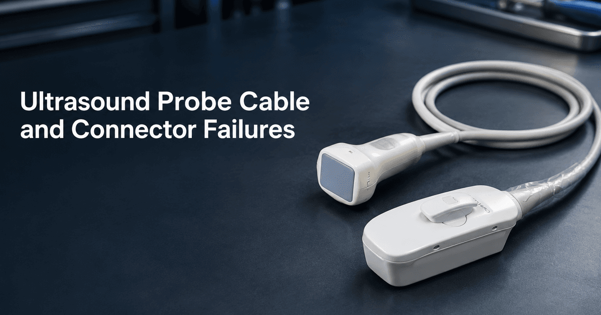
A transducer that "suddenly died" is rarely a dead array. On the bench, the faults that look electrical at the machine end — intermittent dropout, a band of missing elements, noise that appears only when the operator moves the patient — usually sit in the last thirty centimetres of cable and in the connector shell. The array itself is the expensive, well-protected part. The cable is the part that gets coiled, hung, stepped on and yanked.
This is the sequence we run before quoting a repair, because the answer changes the decision: a cable or connector repair returns the probe to service at a fraction of replacement cost, while a failed array or a delaminated lens usually ends the probe's economic life. Getting the sequence wrong sends good probes to scrap and bad ones back to the ward.
Why the cable fails before the array does
Every flex cycle concentrates stress at one point: where the cable jacket meets the strain relief boot, and where the boot meets the connector shell. Inside that bend radius, the individual coax conductors, the shield braid and the drain wires are all moving relative to one another. The jacket is designed to hold them still. Once the jacket splits — a split that is often two millimetres long and invisible unless you pull the boot back and look — the conductors take the movement instead.
The failure mode that follows is characteristic. It is not a clean open circuit. It is a changing resistance: fine when the probe hangs still, intermittent when the cable is loaded at a particular angle. That is why a probe can pass a quick continuity check on the bench and still drop elements on the ward.
Step 1 — Prove the fault is in the probe, not the system
Before opening anything, isolate the variable. Move the probe to a second port on the same system, and a known-good probe into the original port. If the dropout follows the probe, you are working on the right component. If it follows the port or the system, stop — you are about to spend money on the wrong part.
Then load the cable deliberately. With live imaging on a tissue-equivalent phantom, flex the cable at the boot, then at the mid-span, then rotate the connector in its socket. Watch for element dropout, a dark band, or a sudden drop in overall gain. A fault that appears only at one angle of one specific movement is a cable fault until proven otherwise.
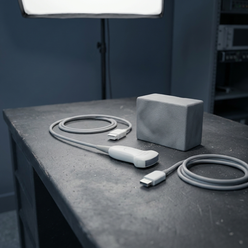
Step 2 — Inspect the connector end under magnification
The connector is where most cable faults become visible. With the probe unplugged and the shell cleaned, inspect four things in this order:
- Pins — bent, recessed or discoloured pins. A single bent pin can short an element pair and produce a band that looks exactly like a failed array.
- Latch and housing — a cracked latch lets the connector seat at an angle, which produces intermittent contact that mimics a cable break.
- Boot-to-shell junction — look for a split, a bulge, or a hardened, shiny section of jacket where the plasticiser has migrated out.
- Cable jacket at the boot — this is the single most common fault site on the whole assembly.
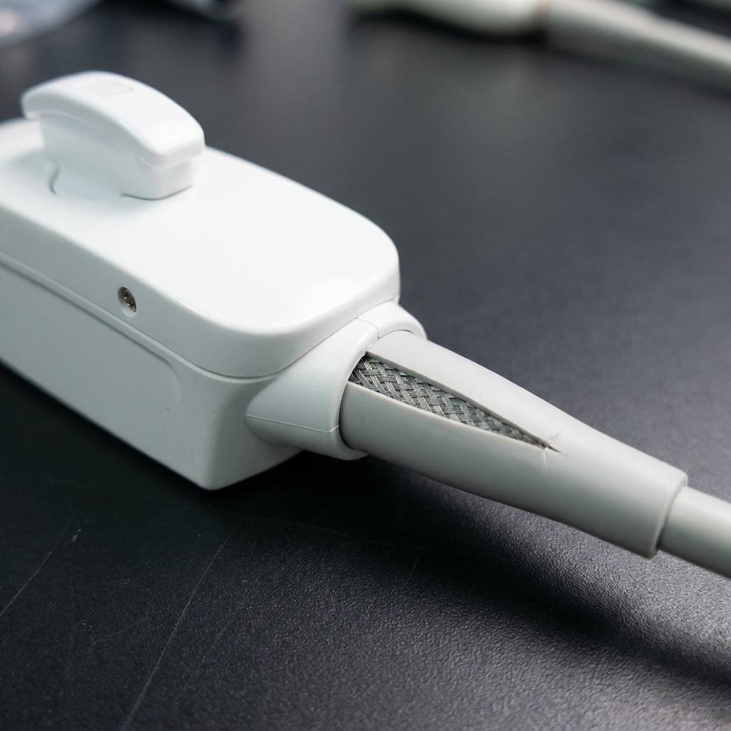
If the split is short and the shield is intact, the repair is a boot-and-jacket rebuild: cut back the damaged section, re-terminate, re-mould or sleeve the boot, and re-test. If the shield is broken or the conductors are visibly displaced, the connector end has to be re-terminated, and the probe needs a full electrical test afterwards — not just a continuity check.
Step 3 — Test the array only after the cable is cleared
Only when the cable and connector are proven good does an array test mean anything. Scan a uniform phantom and look for:
- a consistent dark band in the same position at every angle and every depth;
- dropout that persists with a different cable route and a different port;
- element-to-element variation that survives a gain normalisation.
A pattern that is stable, geometric and independent of cable position points to the array or the lens. A pattern that moves when the cable moves points back at the cable. This single distinction is what separates a repair quote from a replacement quote.
Step 4 — Decide repair or replace
Use the inspection result, not the purchase price, as the decision input:
- Cable or boot damage, array clean — repair. The probe keeps its sensitivity, its element count and its compatibility with the system.
- Connector re-termination required, array clean — repair, with a full post-repair image test and a recorded element map.
- Lens delamination, cracked face or a confirmed dead element group — usually replacement. Repair cost climbs toward the value of a refurbished unit, and the residual risk of a second failure is high.
- Unknown history plus any two of the above — treat as replacement unless the model is still supported and a verified refurbished unit is not available.
What to record before the probe leaves the room
A repair is only as good as the record that goes with it. Capture the model and serial, the exact fault as the operator described it, the position on the image, the flex angle that reproduces it, and the connector photographs taken in Step 2. When the probe comes back, the same phantom scan and the same flex test are the acceptance criteria — not "it looks fine now".
That record is also what makes a second failure diagnosable instead of arguable. In our experience the probes that come back twice are the ones that were sent out with a symptom and no baseline.